
Part 3: Hardware / Schematic
IMPORTANT! Before we connect anything, it's critical to check the resistance across each axis. With an ohmmeter, measure the resistance from X+ to X-, and the resistance from Y+ to Y-.
If either axis measures less than 300 ohms, you'll need to add current limiting resistors!
We'll be driving both axes with 5V from GPIO pins, so it's critical to limit current well below 20mA. Otherwise, pins will be damaged and/or smoke will escape, neither of which is a recipe for success.
If you measured higher resistances (1k is a common ballpark value), you can omit the resistors from the schematic below, and connect directly to the Arduino pins.
Check Your Pinout
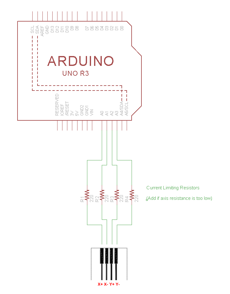
There's no standard pinout for XYZ Pads, so you'll need to look at the traces on your pad and determine which pins are X+, X-, Y+, and Y-. The schematic below is just an example, don't take the pinout as fact!
In following schematic and code example, for consistency's sake, we'll refer to the left conductor as X-, right as X+, top as Y+, and bottom as Y-.
You can always re-orient the pad on your desk, but what's important is getting the axial pairs correct.
Schematic
Welp, There Go the Analog Pins (Not Really)
Analog Input GPIO pins can be a valuable commodity, so you might be wondering if we really need to use up four of them.
The answer is "no". If you check the code example in the next section, you'll observe that we're actually only reading from X+ and Y+. So you could remap two pins to digital GPIO, if needed.
The only reason we're using analogs for all four is the convenience / neatness of plugging it all into one header.
Got it wired? Good, let's move on to a firmware example...