
The Basics
Force-sensing resistor (FSR) inks are typically screen printed and cured on a Mylar™ film. Two basic FSR configurations are the "ShuntMode™" and "ThruMode™".

ShuntMode™ FSR Construction
ShuntMode™ FSRs are made by screen printing silver conductive interdigitated finger patterns on one film and an FSR element on the other, then facing them toward each other.

ThruMode™ FSR Construction
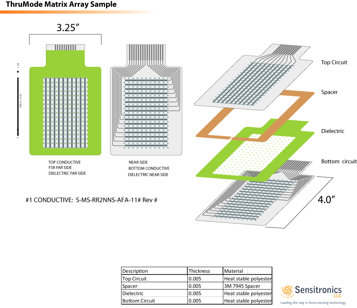
ThruMode™ devices are constructed by screen printing a solid conductive pad on each substrate overprinted with an FSR element, which are faced toward each other.
View ThruMode FSR Construction Example...

SPACER HEIGHT & ID
As with a typical membrane switch, the two substrates can be spaced apart using various thicknesses of spacer material like 3M 467 double stick adhesive. The spacer height and inside diameter or thickness of the spacer, and the open area (ID) of the spacer, as well as the thickness of the top or deflecting film, will mechanically determine the amount of force required for the two surfaces to come into contact.
A typical conductive membrane switch is fully conductive when force is applied and contact is made. A force-sensing resistor can be in contact and maintain a high resistive state with light force in a "preloaded" condition. In this instance, a threshold circuit is used to set the limit at which the device is considered "in contact".
DIELECTRIC DOTS
Dielectric dot patterns can also be used for spacing the two layers apart. The frequency or spacing and height of the dots determine the amount of force needed for activation. The closer the dots are to each other, the more force is required to activate the sensor.
MOUNTING THE FSR
The FSR device works best when mounted to a rigid or semi-rigid backed surface so that when the force is applied to the device, there is a surface to push against. The FSR device can be adhered to a surface with an adhesive such as 3M 467.
THE ACTUATOR
The actuator system is critical for improving the part-to-part reproducibility of the FSR device. The actuator references the device, or means, in which the FSR device is "touched" or actuated. As the flexible upper substrate deflects and yields to the force applied to the actuator, initially there is a small area of contact between the FSR element and the circuit. As the force is increased, the area of contact also increases and the output becomes more conductive. These principles are minimized and a less dynamic range is accomplished when both substrates are rigid.
As long as the force is applied consistently, cycle-to-cycle repeatability is maintained. A thin elastomer, such as silicone rubber, placed between the actuator and the sensor, can be used to absorb some error from inconsistent force distribution.

Designing the actuator to ensure proper loading of the sensor is critical to a consistent FSR device. The actuator material is chosen specific to the application.
Make sure the actuator is about 20% smaller than the inside diameter of the spacer opening (dependent on spacer height). If the actuator is too close to the spacer, it can block the force.
PEEL N STICK
We offer a low-cost Peel & Stick solution for the ShuntMode device. Etch a .007" space and trace (immersion gold) conductive finger pattern on a PCB. Simply peel the liner paper from the FSR element and adhere it to the PCB.
INKS / SPACE-and-TRACE EFFECT
The space-and-trace widths will affect the output of the sensor. The wider the space-and- trace the more resistive the output. More resistive inks tend to be more linear and will tolerate higher forces. More conductive inks can work better for some finger activation devices.
PROTOTYPING WITH REPOSITIONING TAPE
Repositioning tape and permanent tape can be purchased from most office supply stores. Use the repositioning tape for prototyping. When the prototyping is complete, peel the repositioning tape off, and use the permanent tape for the more robust, final version.
OTHER TIPS
An FSR is not a strain gage or load cell. It will consistently deliver a characteristic curve and can achieve 2% accuracy with a well designed actuator system. A calibration system is suggested for applications where higher accuracy is required. Most application will achieve 5% to 15% accuracy, depending on the actuation system.
Force-sensing resistors are custom made and screen printed for specific designs and applications. Our sample kit is designed to help the designer become familiar with how a force-sensing resistor works, but is not meant to fulfill all design needs.
Keep the current low, below .5ma. Even though we use the best engineered polymer resins, overheating will destroy the device.
DRIFT
Sensitronics has met the formidable challenge of the inherent Force-Sensing Resistor characteristic known as “drift” with our patent-pending LowDrift Force-Sensing Resistor. Now, when a dead weight is placed on an FSR, the resistance value remains relatively steady.